3D import object mappings
Plant Modeller can import IFC beams and plates as native CADMATIC objects if the parts are mapped in a 3D Import Object Mappings configuration and the configuration is selected in the 3D-import options that the IFC import process is using.
You can define the mappings either in the library or the project database, but the CADMATIC objects must be in that same database. The easiest way to get the IFC data for the mappings is to scan them from IFC files, but you can also define a name and description for IFC parts manually.
Creating a new mapping configuration
Create a 3D Import Object Mappings configuration to allow Plant Modeller to import IFC beams and/or plates as CADMATIC objects.
Do the following:
-
In Plant Modeller, select File > Environment > All Library and Project. The Project Environment dialog opens.
-
Browse to [library or project] > 3D Import Settings > 3D Import Object Mappings.
-
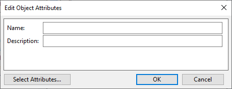
Select New > 3D Import Object Mappings. The Edit Object Attributes dialog opens.
-
Enter a descriptive name for the settings object and click OK.
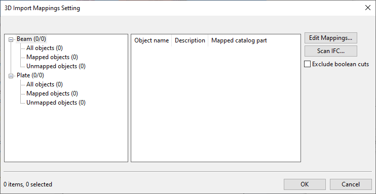
The 3D Import Mappings Setting dialog opens.
-
Select the option Exclude boolean cuts if you want to import objects so that end cuts are preserved but Boolean cuts are removed.
-
Define the IFC objects.
-
To get both beams and plates from an IFC file, do the following:
 Show/hide details
-
In the 3D Import Mappings Setting dialog, click Scan IFC.
-
Select the IFC file to be scanned, and click Open.
-
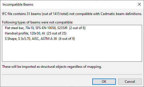
You might be prompted that some "incompatible" IFC beams will be imported as structural objects. This can happen, for example, if the IFC file contains a bended beam. Click OK to continue.
-
-
To get only beams or plates from an IFC file, do the following:
Show/hide details
-
In the 3D Import Mappings Setting dialog, select either Beam or Plate from the category tree, depending on which type you want to define, and then click Edit Mappings. The mappings dialog opens.
-
In the mappings dialog, click Scan IFC.
-
Select the IFC file to be scanned, and click Open.
-
If you are scanning beams, you might be prompted that some "incompatible" IFC beams will be imported as structural objects. This can happen, for example, if the IFC file contains a bended beam. Click OK to continue.
-
-
To define an IFC beam or plate manually, do the following:
Show/hide details
-
In the 3D Import Mappings Setting dialog, select either Beam or Plate from the category tree, depending on which type you want to define, and then click Edit Mappings. The mappings dialog opens.
-
In the mappings dialog, click Add.
-
Enter a name and description (as found in IFC files), and click OK.
-
-
To delete IFC beams or plates, do the following:
Show/hide details
-
In the 3D Import Mappings Setting dialog, select either Beam or Plate from the category tree, depending on which type you want to delete, and then click Edit Mappings. The mappings dialog opens.
-
In the mappings dialog, select the IFC objects you want to delete from the pane on the left, and click Delete.
-
-
-
Map the IFC objects to CADMATIC objects.
Show/hide details
-
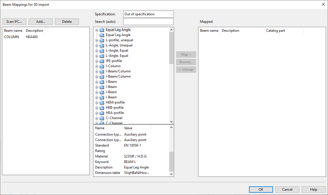
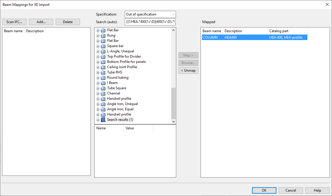
In the 3D Import Mappings Setting dialog, select either Beam or Plate from the category tree, depending on which type you want to define, and then click Edit Mappings. The mappings dialog opens, listing the unmapped IFC objects on the left, the available CADMATIC objects in the middle, and the mapped IFC objects on the right.
-
In the left pane, select an IFC object (or objects) that you want to map to a CADMATIC object.
Selecting an IFC object generates a Search (auto) string that tries to find a matching CADMATIC part type and part size from the database.
-
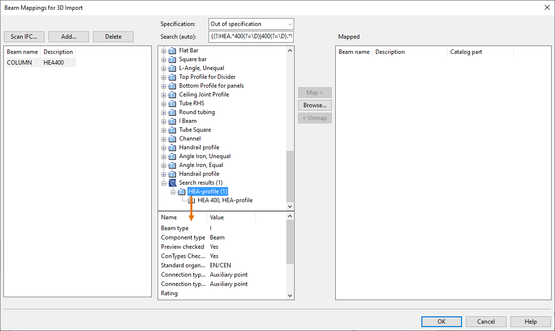
If a matching CADMATIC object is listed, select the correct part size from the list.
-
If several matches are listed and you are not sure which one to select, you can click a part type to see its details in the information pane.
-
If there are no matches, you can try to customize the search string:
-
You can use the asterisk * to represent any sequence of characters and the question mark ? to represent a single character.
-
You can use regular expressions for pattern matching.
-
You can use regular expressions with ECMAScript pattern matching if you enclose the search string in curly brackets:
{\b(\w+\s*)+}
-
Note: Editing the search string turns off the automatic search. If you clear the search field, automatic search is enabled again.
Instead of using the search, you can click Browse to select the CADMATIC object from an object browser dialog.
-
-
To map the selected IFC objects to the selected CADMATIC object, click Map. The mapping is shown in the right pane.
-
When you have done all the required mappings, click OK.
-
-
Click OK. The configuration object is ready to be used in IFC imports.